The oil level sensor of a certain model is a reed switch type structure, and the sensor gear position failure is manifested as no reaction of the oil gauge pointer below 3/4 gear. After investigation and test analysis, the cause of the failure is to adjust the mounting angle of the PCB when the sensor is produced. However, at this time, some protective resin is filled between the PCB and the outer plastic tube, the resin hinders the twisting of the PCB, and the external force is applied to the reed switch. The reed switch is damaged in 3/4 gear. After a certain period of use, the reed cannot be disconnected. The maximum output resistance of the sensor can only reach the resistance of 3/4 gear, so the oil gauge pointer is in 3/4 gear. There is no response below the bit. In order to avoid such problems, the outside of the PCB board is no longer filled with resin, and both sides of the PCB board are protected by a sealant and a rubber seat.
1. Oil level sensor failure phenomenon
A certain type of oil level sensor has a fault phenomenon on the whole vehicle. The specific performance is that the oil gauge pointer has no response below 3/4 gear, that is, the oil quantity decreases and the pointer does not move. The pointer can swing normally above the oil meter 3/4 gear. The same fault occurred on 3 cars and the sensors were in the same batch.
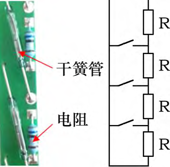
Sensor circuit schematic
The oil level sensor circuit and principle are shown in Figure 1. The reed switch is a magnetic switch consisting of two magnetic reeds wrapped by a glass tube. The oil float is equipped with permanent magnets. When the reed switch is attracted by the permanent magnet, the resistance of the reed switch is short-circuited due to the oil float. As the oil level floats, the oil level has a corresponding relationship with the sensor resistance. The maximum design resistance of the sensor is 107.8 Ω, which corresponds to the oil gauge of the oil gauge. The maximum output resistance of the faulty component is 29Ω, corresponding to the 3/4 gear of the oil meter. There are two reasons for this failure: one is that the circuit board itself has a short circuit, and the other is that the reed switch fails and cannot be disconnected. Both can short-circuit the resistance below 3/4, so that the maximum output resistance is only 29 Ω.
2, oil level sensor troubleshooting
2.1. PCB board short circuit troubleshooting
The structure of the sensor is shown in Figure 2. From left to right, the casing, plastic tube, epoxy resin and PCB board are in order. The PCB board is placed in a plastic tube and then placed in a sleeve. The plastic tube is first filled with a sealant, and the PCB board is fixed and then filled with epoxy resin. After the resin is cured, the PCB board is protected and sealed. The epoxy resin is fluid during filling and is hard after curing, which makes it difficult to completely disassemble the faulty part.

Figure 2 Schematic diagram of the sensor structure
Check whether there is a short circuit in the PCB board, and expose the PCB board wiring surface. The PCB board after being soaked by the epoxy resin dissolving agent is shown in Figure 3. The solder joint is smooth and firm, and no soldering phenomenon is seen. The PCB board short circuit problem can be eliminated. . Since the dissolving agent has a corrosive effect on the reed switch glass, the reed switch after immersion has been damaged.
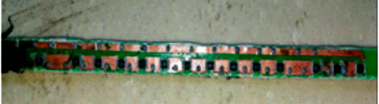
Figure 3 PCB board disassembly diagram
2.2. Reed switch failure investigation
The reed contact of the reed switch is sealed in the glass tube, the inside is filled with inert gas, and the contact contains an inert precious metal crucible, which can reduce the loss of the arc discharge on the contact surface. When the glass tube of the reed pipe is damaged, the internal inert gas leaks and the life of the reed contact is shortened.
Before the reed pipe is welded, the pin needs to be bent by 90° in a straight line. After the pin is bent, it is inserted into the PCB board hole for welding. The state before and after the pin is bent is shown in Fig. 4. The bent pin generally uses special tooling, and the tooling has a groove and magnetic, which can prevent the reed switch from being displaced when the pin is bent, and avoid the reed switch when the corner is broken, even if the reed pipe is damaged, after welding It will also be discovered during the test. During the inspection at the production site, a batch of reed switches were randomly bent. After testing, the performance of the reed pipe was up to standard.
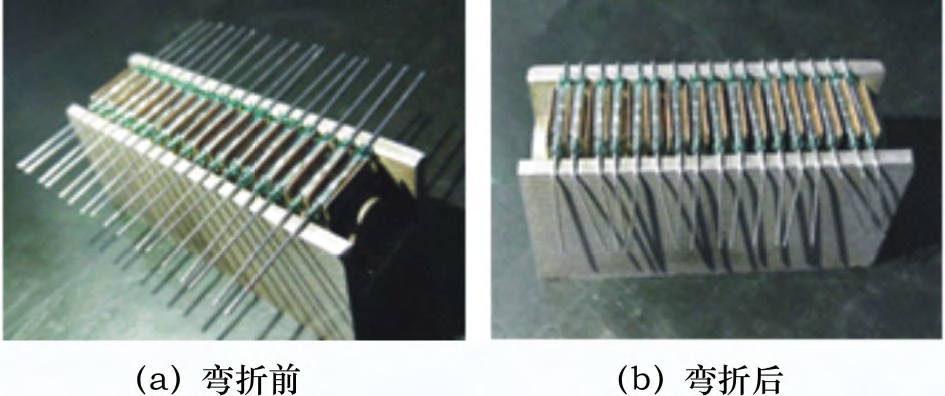
Figure 4 Schematic diagram of the state of the reed pipe before and after bending
The reed switch cannot be disconnected because the reeds are stuck. In order to verify the adhesion of the reed switch, the following test was carried out: the reed switch was used as a magnetic switch and the oil pump motor in series, the power supply voltage was 12 V, and the reed switch was pulled by the permanent magnet. After the circuit was connected, the motor was running. A spark is flashed between the tube springs. After a period of time, the permanent magnet is removed, the motor is still running, the reed switch cannot be broken and fails, and the heat generated by the spark causes the reeds to stick together. However, this phenomenon does not occur on the whole vehicle. The current in the reed switch reaches 0.9 A during the test, which has exceeded the normal working current of the reed switch by 0.5 A. This test is only to verify the failure mode of the reed switch.
When reviewing the sensor production record, it was found that the batch of faulty parts was adjusted during installation to adjust the mounting angle of the PCB board in the casing. This is to make the reed switch away from the pump core and reduce the interference of the magnetic field on the reed switch. When the angle of the PCB is adjusted, the lower part of the PCB has been filled with resin, and the resin has gradually solidified. At this time, the PCB board is distorted by external force, which may cause damage to the reed switch. When disassembling another faulty part, it was found that the PCB board was obviously distorted. As shown in Fig. 5, the failure occurred in the 3/4 speed because the torsional deformation was the largest.
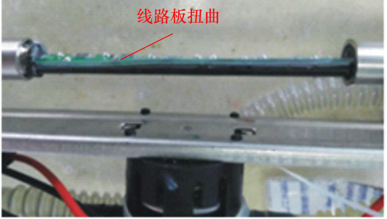
Figure 5 Schematic diagram of the PCB board twisting inside the casing
To verify the speculation, a normal PCB board is artificially twisted at a certain angle, and then the PCB board is connected to the oil gauge and placed in the electromagnetic coil. The electromagnetic coil closes the reed switch at a frequency of 10 times/min. After 8 hours, the sensor The maximum output resistance is 29 Ω, which is consistent with the faulty part of the vehicle.
When the failed reed switch is placed under a 300x magnifier, it can be seen that the reed contacts have no gap, while the normal reed contacts have visible gaps, as shown in FIG. The normal reed switch can observe the reed pull action after the magnetic field is close, while the failed reed switch does not respond.
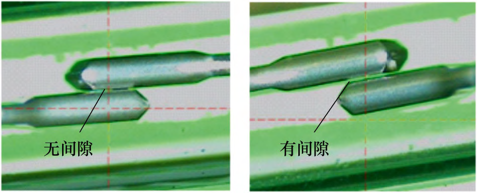
Figure 6 Schematic diagram of the reed gap
The oil level sensor fails after the PCB board is twisted and used for a period of time because the reed gap is reduced. When the magnetic field of the oil float makes the reed switch at the time of opening, the arc discharge is easily formed, and the discharge spark heat causes the reed to touch. After the sticking, the 3/4 retaining springs are stuck, and the following gears are invalid.
3. Sensor failure rectification measures
The function of filling the resin around the oil level sensor PCB board is to improve the shock resistance and the sealing property. However, when the sensor is faulty, it is not suitable for complete disassembly, which makes the failure analysis difficult, and the resin requires a long curing time and the production efficiency is not high. Due to the need to manually load the PCB into the casing, it is easy to adjust the angle.
Filling the resin causes damage to the reed switch. In order to avoid this problem, the sensor no longer fills the epoxy in the plastic tube, and changes the sealing glue to a small amount at both ends. The sealing glue does not cover the circuit part, and the rubber board is used to fix the PCB board at both ends.
4. summary
The 3/4 gear of the oil level sensor fails because the mounting angle of the PCB board is adjusted when the sensor is produced, and the reed switch is damaged by the external force twisting the PCB board. After a period of use, the arc discharge between the reeds causes the reed contacts to stick and cannot be broken. On, the maximum resistance of the sensor stops at 29Ω, and the minimum oil level of the oil meter can only be displayed to 3/4.

Scan the QR Code with WhatsApp


WeChat
Scan the QR Code with WeChat